| Author |
Topic: Gretsch 6161 (Valco) tube amp problem - FIXED! |
Bill Sinclair
From:
Waynesboro, PA, USA
|
 Posted 10 Feb 2020 12:26 pm
 |
|
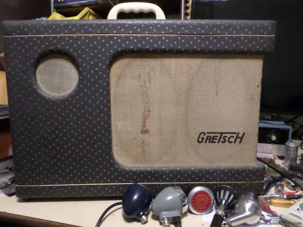
EDIT: Amp now works - read my post further down with pictures of the amp if you're interested.
>>>>>>>>>>>>>>>>>>>>>>>>>>>>>>>>>>>>>>>>>>>>>
For you tube amp lovers with more bench time than me (I'm more of a hobbyist):
I was recently gifted one of those cool Gretsch amps with the two 6 X 9 oval speakers (and a tweeter!). 2 6V6’s on the output, 2 6SQ7 triodes (preamp and tremolo) and a 12AX7 for the (long tail*)PI. Replaced all the electrolytic and paper caps and installed a 3 prong cord. All of the carbon resistors were pretty close to the 10% tolerance so I let them be. I figure this amp is a keeper since it was made the same year as me (1957) but I can only get about 1.8 clean watts out of it! And less than 3 very distorted watts at full volume. Something ain’t right!
Picture 1 shows the two undistorted phase inverter outputs at about half volume (1KHz, 100mV RMS input)
Picture 2 shows one of the phase inverter outputs in ch 1 and the plate of one of the 6V6s in ch 2. Not as much gain as I would have expected and a fair amount of distortion already.
Picture 3 shows ch 2 at the 2 ohm speaker.
I noticed that the 6V6 plate voltage drops from 302 VDC at idle to 275V at 1/2 volume and 265V at full volume. Is this a normal amount of "sag" or excessive? If that's not normal, I suspect a problem with my replacement filter caps.
I'll post more pics, including a schematic, shortly.
* edit: I was wrong, it's a para phase inverter, not long tail


Last edited by Bill Sinclair on 16 Mar 2020 5:44 pm; edited 2 times in total |
|
|
 |
Bill Sinclair
From:
Waynesboro, PA, USA
|
Posted 10 Feb 2020 12:49 pm
|
|
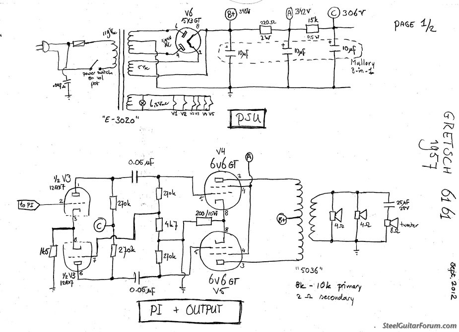
Next picture is the two PI outputs at full volume followed by the top PI and bottom speaker signal. Also, a hand drawn schematic of the power supply and power output section that I found on the internet. It's pretty close except that mine has a center-tapped filament winding. And my B+ voltage is lower. Hmmm... might be answering my own question here.


 |
|
|
|
J Fletcher
From:
London,Ont,Canada
|
Posted 10 Feb 2020 1:07 pm
|
|
| So , what is the voltage at pt A , which is the 6v6 screen supply ? |
|
|
|
J Fletcher
From:
London,Ont,Canada
|
Posted 10 Feb 2020 1:59 pm
|
|
Might be a weak rectifier . Yeah your high voltage is a fair bit lower than the schematic shows. The voltage on the shared 6v6 cathode resistor should be around 20 to 25 volts . Is it ? Either you are drawing excessive current , or the 5Y3 is weak , if the voltages on the schematic are correct.
Do you have another pair of 6v6's to try? Voltages would be useful to know. Jerry |
|
|
|
Bill Sinclair
From:
Waynesboro, PA, USA
|
Posted 10 Feb 2020 2:28 pm
|
|
| I've tried 3 sets of 6V6's, 2 5Y3's and 4 12AX7's. Results are pretty much the same. Currently running with a matched pair of new Rubys. It currently has a 330 ohm cathode resistor that is dropping 21 volts at idle. About 30 mA per tube which according to the Weber site, is 70% dissipation with a 300VDC plate voltage. That voltage drop goes up as you crank the volume (I don't recall how much). The output tube plate voltage drops a full 40 volts from idle to full volume though. Is that normal? As I recall, the screen voltage follows the B+ within 5 volts but I'll double check that. What range the screen voltage needs to be is one of those questions I have. |
|
|
|
Ken Fox
From:
Nashville GA USA
|
Posted 10 Feb 2020 3:21 pm
|
|
| Have you checked the two .05uf at the grids of the 6V6 for DC leakage? |
|
|
|
Chris Reesor
From:
British Columbia, Canada
|
Posted 10 Feb 2020 4:09 pm
|
|
The voltage sag does seem excessive. Have you tried a new 5Y3 or 5AR4? I doubt this is a filter cap issue.
The idle current sounds about right, and shouldn't increase enough when signal is applied to cause that much sag.
The output stage seems to clip symmetrically, which suggests it is not a partially shorted output transformer, which I have seen cause low power output and high distortion.
It might be a good idea to check for parasitic oscillation above the audible frequency range.
I'm surprised there is no bypass cap for the output stage cathode resistor. Did the chassis show any signs of old repair work when you got it? You should expect to get 10-12 fairly clean watts out of that setup, even with a 300 V. plate supply.
Good luck with this problem.
_________________
Excel Superb U12, MIJ Squier tele, modified Deluxe Reverb RI, Cube 80XL, self built acoustics & mandolins |
|
|
|
Fred
From:
Amesbury, MA
|
Posted 10 Feb 2020 6:18 pm
|
|
The available schematics show a 35uF 50v cap bypassing the output cathode bias resistor. Anything from around 25 to 50 uF would work. That would get rid of the negative feedback and stabilize the operating point.
There are overdrive conditions where the grid on an output tube will conduct. That can be controlled with a resistor in series with the grid. I’d have to look up some old notes, but something from 1-10k should work. It’s probably a good idea to bypass the common cathode resistor in the phase inverter.
Fred |
|
|
|
Bill Sinclair
From:
Waynesboro, PA, USA
|
Posted 10 Feb 2020 9:04 pm
|
|
Thank you guys so much for your responses. Some things for me to check and think about.
Ken,
There was about 7 mV on the 6V6 grids at idle, which I didn't think was that bad but I just checked with the volume cranked and there was -2.2 V on one and -5.3 on the other. Is that an indication of anything? I used a couple of NOS Aerovox .05 coupling caps in the final stage. They measured spot on for capacitance but I don't have a leakage tester (until they're in the amp anyway). Another potentially significant fact is that while the screen voltage is a couple volts lower than B+, it is actually about 10 volts higher than the plate voltage, at full volume anyway. Is that just normal due to the voltage drop across the OT transformer primary?
Chris,
I've tried a couple of 5Y3's from my used stash but I'll try one from a known good amp. When I received the amp it had no output other than a 120Hz (I think) hum. Previous owner said it just quit one day. Replaced all the electrolytic and paper caps (all way out of tolerance) and bumped up the cathode resistor and this is where I am. At least it passes a signal now.
Fred,
The two schematics I have don't show a bypass cap on the output cathode resistor and the amp didn't show any sign of having had one. There is a 25/25 bypass cap on the preamp stage though. I'll try to show a copy of that schematic in the morning. One of the things that it shows that the hand drawn schematic doesn't is that the center tap of the filament winding connects the 6V6 cathodes instead of directly to ground. Flipping through some other amp schematics I see that is fairly common. |
|
|
|
Bill Sinclair
From:
Waynesboro, PA, USA
|
Posted 11 Feb 2020 2:32 pm
|
|
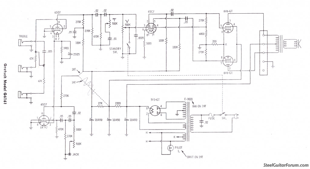
Rehearsal tonight so I won't have a chance to get back to this amp today. Gonna try to post a picture of the other schematic I have though. There are a lot of different versions of this model amp. Later ones have top mounted controls and some have 6973 output tubes! Mine has rear mounted controls and 6V6 outputs. This diagram matches except that mine has a 12AX7 phase inverter instead of the 6SC7, with 270K plate resistors instead of 100K.
 |
|
|
|
Donny Hinson
From:
Glen Burnie, Md. U.S.A.
|
Posted 11 Feb 2020 8:36 pm
|
|
| Ken Fox wrote: |
| Have you checked the two .05uf at the grids of the 6V6 for DC leakage? |
That was my first thought...bias screwed up, most likely by leaky capacitors. |
|
|
|
Ken Fox
From:
Nashville GA USA
|
Posted 13 Feb 2020 10:17 am
|
|
Seems the problem is in the phase inverter section. Do all the resistors check out there?
Here’s a great video that’s covers phase inverters
https://youtu.be/U6By31V9fDo |
|
|
|
Bill Sinclair
From:
Waynesboro, PA, USA
|
Posted 13 Feb 2020 7:03 pm
|
|
Ken,
Thanks. I watched that video a while back but when I re-watched it tonight I realized that I incorrectly identified this as a long tail inverter when it's actually a paraphase. Uncle Doug's videos are great.
All the resistor values are within 10% and I've tried four different 12AX7 and a 12AT7 tube. I did try changing the cathode resistor from the 2.2K that was in the amp to a 1.5K as shown in the hand drawn schematic but it made no difference.
What makes you suspect the inverter section? Is it the asymetrical clipping on the top channel of the o'scope in the fourth picture? I wasn't sure if that was normal or not. The very first picture, though, shows both inverter outputs prior to clipping (about 1/2 volume) and they look pretty good. The next picture shows one of the inverter outputs in ch 1 (still at 1/2 volume) and one of the 6V6 plates in ch 2 and there's already something distorted and jittery happening on that plate. That's why I thought the inverter stage might be okay. At this point my troubleshooting on this amp is starting to feel like speculative fiction though!
I haven't tried Fred's suggestions of adding cathode caps and perhaps grid resistors because the amp didn't have them in the first place. It doesn't seem like it would hurt to clip on a couple cathode caps just to see what happens though so I'm willing to give it a try. |
|
|
|
Ken Fox
From:
Nashville GA USA
|
Posted 14 Feb 2020 5:55 am Amp
|
|
Is there any chance the grid of the inverter tube is getting DC from the previous stage?
I would have thought the inverter outputs would be symmetrical |
|
|
|
Fred
From:
Amesbury, MA
|
Posted 14 Feb 2020 2:12 pm
|
|
The scope photo of the two phase inverter outputs looks like what I’d expect to see. With this type of phase inverter the second stage is fed a small signal from the output of the first stage. That means it will amplify any distortion from the first stage. The scope shows a clipped output from the first stage. The second stage amplifies that and also clips. These stages only clip one side of the waveform.
The second thing I see is the outputs are 70-100 volts peak to peak. Anything over the bias voltage of 21v will distort badly. When the grid goes more positive than the cathode it starts acting as a suppressor. Basically the voltages on the output stage are all over the place when it’s driven hard. There’s times that the tubes are in full conduction so a large power supply drop isn’t that odd. How much current is the power transformer rated for? I’d use 20uF for the first power supply capacitor. It helps with transients but won’t do anything for continuous full output conditions.
These amplifiers weren’t designed for full volume hard clipping conditions. Bypassing the bias resistor on the output tubes will help. Global feedback from the secondary of the output transformer has become almost universal. It helps to stabilize things a lot but I prefer the livelier feel of no global feedback.
The common cathode resistor in the phase inverter looks too small to me. I’d try something in the range of 3-5K, unbypassed. The gain will come down a bit (you have a lot more than your need) and the additional feedback will help stabilize things.
Fred |
|
|
|
Bill Sinclair
From:
Waynesboro, PA, USA
|
Posted 16 Mar 2020 5:41 pm Update
|
|
Thought I'd post an update on my amp problem. It turned out to be an open winding in one leg of the output transformer primary. I'm not sure how I got readings when I measured earlier. I was certain that I measured 300 VDC on the plates of both 6V6s. Also, I wrote down resistance measurements for both sides of the center tap. Either the winding was about to open or I just measured in the wrong place. My amp tech friend put it on his bench and that was the first thing he checked. "I'm not getting any reading here!" I felt like a knucklehead. He wouldn't even charge me. I took it back home and scrounged an appropriate output transformer from an old Newcomb record player chassis, wired the speakers for 8 ohms and voila! A solid 12 watts before clipping. Now it sounds like a cathode biased Valco amp is supposed to. Many thanks to those of you that took the time to make suggestions. I learned quite a bit from the process.
Here's the troublemaker:

Last edited by Bill Sinclair on 17 Mar 2020 6:37 am; edited 1 time in total |
|
|
|
Jack Hanson
From:
San Luis Valley, USA
|
Posted 16 Mar 2020 6:01 pm
|
|
| Impressive harp mic collection. |
|
|
|
Bill Sinclair
From:
Waynesboro, PA, USA
|
Posted 16 Mar 2020 6:40 pm
|
|
| Jack Hanson wrote: |
| Impressive harp mic collection. |
Thanks, that's just a handful of them. Customizing bullet mics is another hobby. There's really only one that I ever gig with anymore, though. It's a biscuit mic that I made from chopping the stem off a Bakelite paging mic and installed a pot on the back. Perfect cup and easily adjust the volume with my pinky. It's the one with the red grill in the picture above and a side view in the middle of this picture. We'll have to chat about harmonica gear, influences and lapsteel restoration sometime Jack.
 |
|
|
|